Lorem ipsum dolor sit amet, consectetur adipiscing elit. Ut elit tellus, luctus nec ullamcorper mattis, pulvinar dapibus leo.
Rain Doesn’t Wait for Levels — So We Engineered a Smarter Way to Drain It
Introduction: The Hidden Challenge in Stepped Architecture
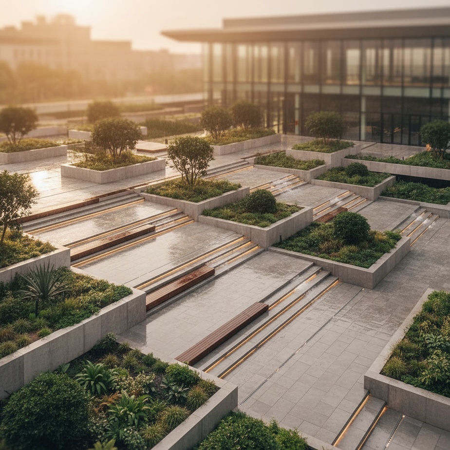
Picture this: A beautifully designed public space with cascading terraces, integrated seating zones, landscaped pockets, and pedestrian pathways that gracefully navigate multiple elevation changes. The architecture is stunning, the user experience carefully curated. But beneath this visible beauty lies an invisible challenge that can make or break the entire project — stormwater management.
When heavy rains arrive, water doesn’t care about architectural intent. It follows one immutable law: gravity. And on a multi-level site with frequent elevation changes, managing this flow becomes a complex three-dimensional puzzle where traditional drainage solutions simply don’t fit.
This is the story of how we engineered a customized stormwater drainage system for such a site — one that respects both hydraulic principles and architectural vision, while remaining practical, maintainable, and cost-effective.
Understanding the Site: Complexity Beyond the Surface
The Architectural Context
The project featured:
- Multiple floor levels with 150-600mm height differences between zones
- Seating terraces integrated into the landscape
- Landscaped pockets with varying vegetation and soil depths
- Pedestrian pathways connecting different activity areas via steps and ramps
- Open courts and gathering spaces requiring unobstructed surfaces
- A central water body serving as the ultimate drainage outlet
Each architectural element was carefully positioned to create spatial hierarchy and visual interest. But from a drainage perspective, this meant dealing with:
- Discontinuous terrain with no single consistent slope
- Limited space for underground infrastructure
- Constraints on excavation depth due to existing foundations and utilities
- High pedestrian traffic requiring minimal surface disruption
- Aesthetic requirements demanding invisible or integrated drainage elements
The Hydraulic Challenge
In conventional stormwater design, maintaining a minimum gradient of 1:100 to 1:150 is essential for achieving self-cleansing velocities in pipes. This prevents sediment accumulation, reduces maintenance frequency, and ensures long-term system performance.
However, when your site features multiple level changes, maintaining this continuous slope becomes problematic:
- Invert Depth Escalation: Starting at shallow depth on an upper terrace and maintaining slope through a lower terrace would require progressively deeper trenching — often exceeding 2-3 meters at transition points.
- Structural Conflicts: Deep excavations risk undermining existing foundations, cutting through structural slabs, or conflicting with underground utilities.
- Construction Complexity: Deeper trenches mean increased excavation cost, shoring requirements, longer construction time, and greater site disruption.
- Maintenance Accessibility: Deeper pipes are harder to access, inspect, and clean, leading to long-term operational challenges.
The fundamental question became: How do we create hydraulically sound drainage across terrain that naturally resists continuous flow?
Design Philosophy: Working With Complexity, Not Against It
Rather than forcing a conventional solution onto an incompatible terrain, we developed a design philosophy centered on three core principles:
1. Segmentation Over Integration
Instead of attempting one unified drainage network, we broke the site into multiple independent drainage zones — each responding to its local topography, runoff characteristics, and architectural constraints. This approach:
- Reduced individual pipe lengths and depths
- Simplified construction sequencing
- Isolated potential maintenance issues
- Allowed phased implementation
2. Gravity-Driven Micromanagement
We identified and leveraged every natural flow path, no matter how small. By placing collection points where water naturally wants to go, we minimized the need to redirect or pump water against natural gradients.
3. Hybrid Surface-Subsurface Strategy
Rather than relying exclusively on underground pipes or surface channels, we created an integrated system that:
- Captured water at the surface where possible (minimal excavation)
- Used short underground crossings only where necessary (at level transitions)
- Incorporated infiltration where soil conditions permitted (sustainable drainage)
Technical Solution: Zone-by-Zone Breakdown
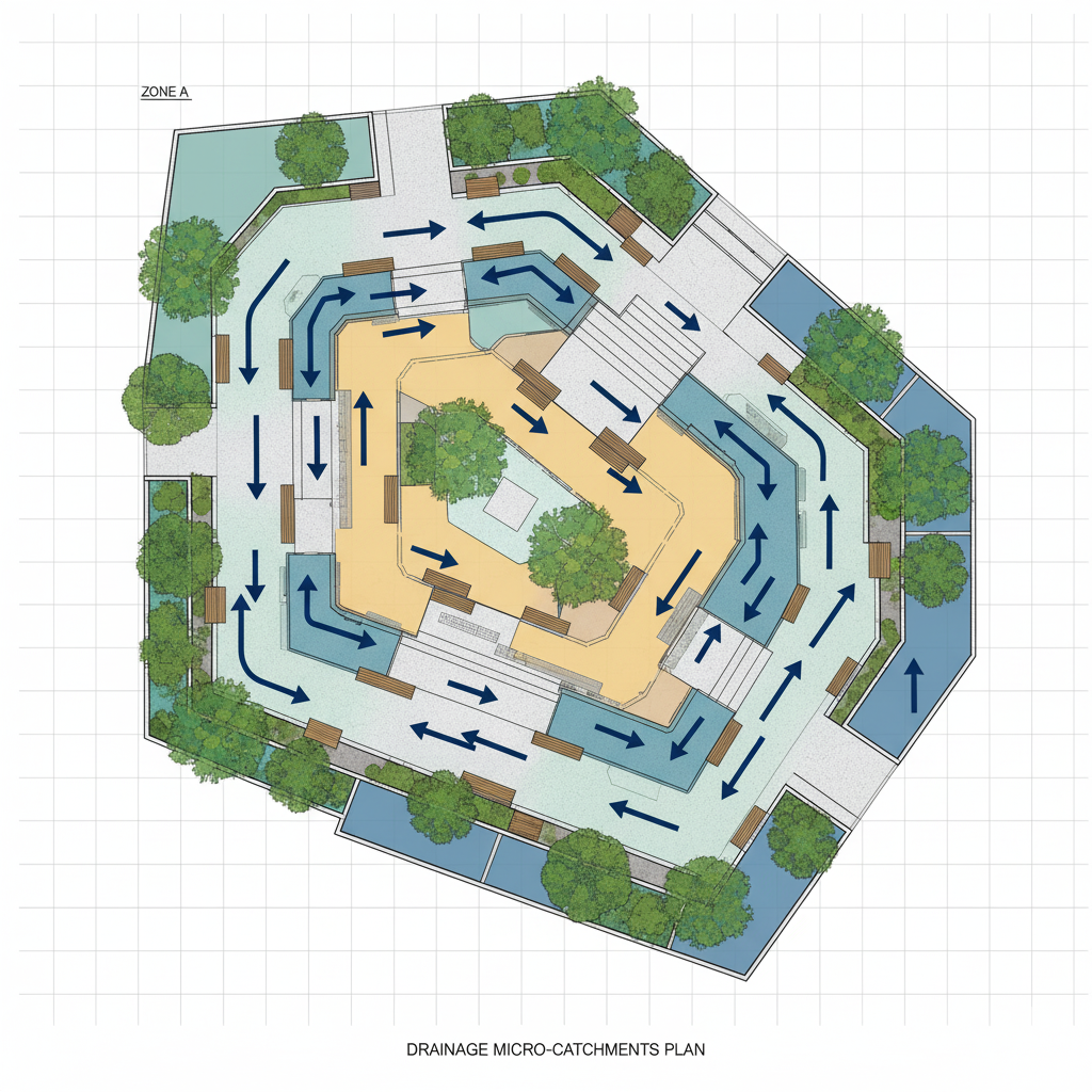
Zone Analysis and Catchment Delineation
The first step was detailed topographic analysis to understand:
- Surface gradients and natural flow directions
- Catchment areas contributing to each drainage point
- Rainfall intensity and runoff coefficients for different surfaces (paved vs. landscaped)
- Level transitions that would interrupt flow continuity
Using a combination of total station surveys and 3D modeling, we created a detailed drainage catchment map that identified seven distinct micro-catchments, each with its own collection and conveyance strategy.
Surface Collection Strategy
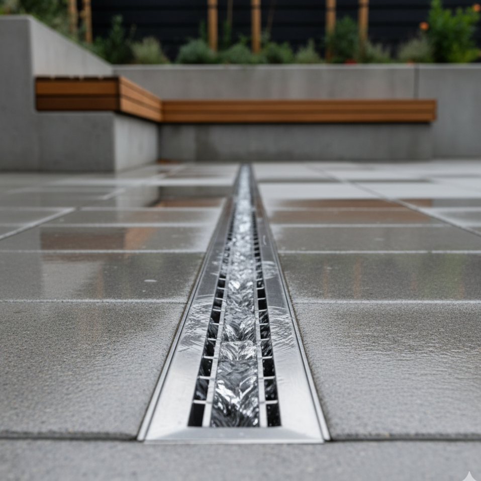
Linear Drains Along Pathways and Terraces
We installed slot drains and channel drains with removable stainless steel or polymer concrete gratings along:
- Terrace edges where seating met lower levels
- Ramp transitions to prevent water cascading onto steps
- Pathway boundaries adjacent to landscaped areas
These drains were:
- Shallow-set (50-100mm below finished pavement level)
- Self-grading with pre-sloped channels matching terrain gradient
- Modular for easy installation and future maintenance
Key Design Detail: We specified grating with heel-safe slots (maximum 10mm width) to ensure pedestrian safety while maintaining adequate hydraulic capacity. Calculations confirmed that 100mm wide channels at 1:100 gradient could handle localized flows from a 1-in-10 year storm event.
Point Drains in Open Courts
In larger open areas without consistent slope direction, we used grated pit inlets positioned at low points identified through topographic analysis. These were:
- Strategically placed to capture sheet flow before it could accumulate
- Equipped with silt buckets for easy maintenance
- Connected to underground pipes via short vertical drops
Underground Conveyance Across Level Changes
At each major level transition (steps, plinths, building entries), we introduced short underground carrier pipes to transfer collected water between zones:
Pipe Sizing and Hydraulic Design
- Used 100-150mm uPVC or HDPE pipes based on flow calculations
- Maintained minimum 1:100 gradient within each segment
- Applied Manning’s equation to verify capacity: Q = (A × R^(2/3) × S^(1/2)) / n
- Incorporated rodding access points every 15-20m for maintenance
Level Transition Details
At stepped areas, pipes were routed:
- Through vertical drops where architectural design allowed (behind walls, under steps)
- Along ramp undercuts where horizontal space existed
- Through specially designed pipe sleeves cast into structural elements during construction
Each transition included inspection chambers at both the upstream and downstream ends, ensuring that any blockage could be quickly located and cleared.
Infiltration Elements in Landscaped Zones
Planted areas presented both an opportunity and a challenge. While vegetation aids water absorption, landscaped zones also tend to shed excess water irregularly, and soil conditions may vary.
Our solution:
Shallow Infiltration Pits
We designed gravel-filled infiltration pits within planting beds:
- Dimensions: Typically 600mm × 600mm × 800mm deep
- Fill: Graded gravel (40-60mm) surrounded by geotextile fabric
- Overflow: Connected to drainage pipes for excess water during heavy rainfall
- Spacing: One pit per 25-30 square meters of landscaped area
These pits served dual purposes:
- Groundwater recharge during moderate rainfall (supporting sustainability goals)
- Overflow drainage during intense storms (preventing surface flooding)
Soil Testing Insight: We conducted infiltration tests at multiple locations and found percolation rates varying from 5-25mm/hour. This confirmed that infiltration alone couldn’t handle peak flows, justifying the hybrid approach with overflow pipes.
Outfall Management
All drainage zones ultimately connected to the site’s central water body, but direct discharge required careful management:
- Silt traps before every outfall point to prevent sediment from entering the water feature
- Energy dissipation structures (rock-lined or concrete aprons) to prevent erosion at discharge points
- Biological filtration layers (vegetated swales) where space permitted, providing additional water quality treatment
Performance Validation: Testing Against Reality
Design Storm Analysis
The system was designed for a 1-in-10 year rainfall event (approximately 90mm/hour intensity for a 15-minute duration based on local meteorological data). This design standard aligns with Indian standards for landscape drainage while providing adequate safety margin.
Hydraulic calculations considered:
- Time of concentration for each micro-catchment (ranging from 2-8 minutes)
- Rational method for peak flow estimation: Q = C × I × A
- Runoff coefficients: 0.85 for paved surfaces, 0.35 for landscaped areas
- Pipe capacity verification using Manning’s equation with safety factors
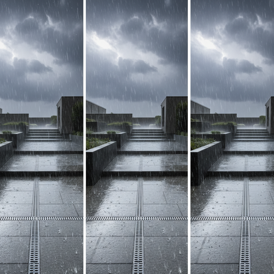
Real-World Performance
During the first monsoon season post-construction, the system was tested by multiple heavy rainfall events, including one that exceeded design intensity. Performance observations:
Successful Outcomes:
- No surface ponding or flooding in any paved areas
- Water cleared from all surfaces within 5-10 minutes of rainfall cessation
- No erosion observed at any outfall point
- Infiltration pits successfully recharged without overflowing during moderate rains
Minor Adjustments:
- One linear drain segment required additional cleaning due to heavy leaf accumulation (subsequently addressed with protective screening)
- Two infiltration pits in densely vegetated areas showed faster saturation than expected, validating the importance of overflow connections
These results confirmed that the segmented, gravity-driven approach successfully managed the complex hydraulic challenges while maintaining system resilience.
Sustainability Considerations: Beyond Water Conveyance
While the primary function was stormwater management, the design incorporated several sustainable features:
Groundwater Recharge
The infiltration pits in landscaped zones allow approximately 30-40% of annual rainfall to percolate into the soil rather than being immediately discharged. Over the course of a monsoon season, this represents significant groundwater contribution.
Reduced Urban Heat Island Effect
By managing water efficiently, we prevented waterlogging that would otherwise kill vegetation. Healthy landscape zones contribute to cooling and air quality improvement.
Water Quality Protection
Multiple treatment elements (silt traps, biological filters, infiltration zones) remove pollutants before water reaches the central water body, maintaining its ecological health and recreational value.
Material Selection
We prioritized durable, recyclable materials:
- uPVC and HDPE pipes (50+ year lifespan)
- Stainless steel and polymer gratings (corrosion-resistant)
- Natural stone and gravel for infiltration zones (no synthetic components)
Conclusion: Engineering as Enabler of Design
This project exemplifies a fundamental truth about engineering: The best solutions are those that enable rather than constrain design vision.
By abandoning conventional approaches and developing a site-specific strategy, we created a drainage system that:
- Works seamlessly with the architectural design
- Performs reliably under real-world conditions
- Remains maintainable and cost-effective
- Contributes to environmental sustainability
Most importantly, the drainage system is invisible to users enjoying the space — which is perhaps the highest compliment for infrastructure engineering. People experience beautiful terraces, comfortable seating areas, and lush landscapes, never knowing the careful hydraulic choreography happening beneath their feet.
In an era where climate change is intensifying rainfall patterns and urban spaces are becoming increasingly complex, such thoughtful, adaptive engineering approaches are not just beneficial — they’re essential.
The lesson is clear: When terrain becomes complex, engineering must adapt, innovate, and evolve — not resist.